
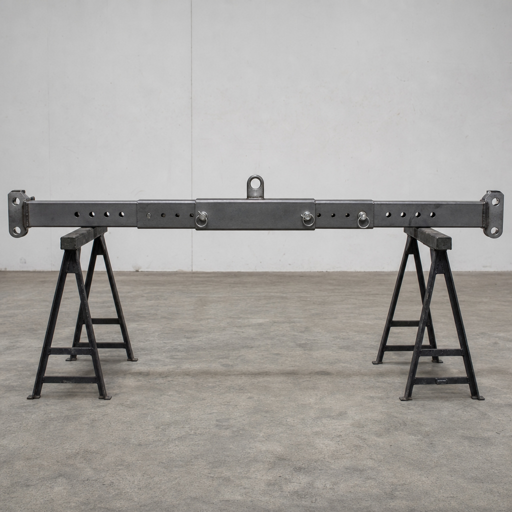
Many lifting beams and spreader beams are built with adjustable lifting points: sliding trolleys running on the main beam, telescoping sections that extend the beam’s overall length, or a series of pre-drilled holes allowing the attachment pins to be repositioned. This flexibility lets one beam serve loads of varying length or lifting-point spacing instead of needing a dedicated beam for every job.
The trade-off is that an adjustable beam’s working load limit is not a single number. As the lifting points move further from the beam’s centre, the bending moment on the beam increases for the same load, so the WLL at full extension is typically lower than the WLL at minimum span. Manufacturers provide this as a table or a set of marked positions on the identification plate, each with its own rated capacity. Using the wrong figure — for example reading the compact-position WLL while the beam is actually set to its longest span — overloads the beam without the load itself having changed.
Before use: confirm which position the beam is actually locked in, physically, not from memory or the last job; read the WLL that corresponds to that exact position from the plate; and check that any locking pins, screw clamps or telescoping locks are fully engaged and secured — a trolley or telescoping section that shifts under load changes the beam’s geometry mid-lift, which is highly dangerous. Inspect sliding surfaces and locking mechanisms for wear, corrosion or bent components, and check that position markings on the beam are legible and undamaged.
- Never adjust an adjustable beam’s span while it is under load or suspended.
- If the position markings are worn away or illegible, withdraw the beam from service until a competent person can re-mark it.
As with any lifting attachment, adjustable beams fall under periodic inspection requirements from a competent body, consistent with Arbeidstilsynet’s framework for lifting equipment.
Standarder: EN 13155 (cranes — safety — non-fixed load lifting attachments)